
Introduction
NOTE: These web pages are documenting a project from 2006 and although the content is still relevant the purpose is mainly to demonstrate the capability of my 'CollectAny' software in it's ability to automatically generate web pages. Some of the photos are low quality due to their original small size.
The Weather Monitor is a home-built weather monitoring system that is based on PICAXE microcontrollers. It allows data readings from a variety of sensors to be collected, stored, displayed and later transferred to a PC. It has been built purely for educational value and enjoyment, although I'm sure it could be put to a serious use if necessary.
The design has gone through a number of improvements and I'm pleased with the overall result, however there is still much scope for further design changes and experiments.
Acknowledgements
• PICAXE is a trademark of Revolution Education Ltd.
• PICAXE Internet Forum where I've learnt a great deal from people's advice and suggestions: http://www.rev-ed.co.uk/picaxe/forum
• Bray's 1-wire barometer: http://www.davidbray.org/onewire/barometer.html
• PICAXE Internet Forum where I've learnt a great deal from people's advice and suggestions: http://www.rev-ed.co.uk/picaxe/forum
• Bray's 1-wire barometer: http://www.davidbray.org/onewire/barometer.html
About the author
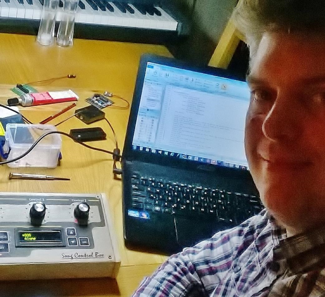
I've always been interested in electronics and have an MENG in Electronic Systems Engineering. However I've spent more time in other IT work than hands-on electronics so to me it's been more of a hobby.
I currently work with SQL databases and .NET apps but always have electronic ideas on the go in the background !
I currently work with SQL databases and .NET apps but always have electronic ideas on the go in the background !
Description
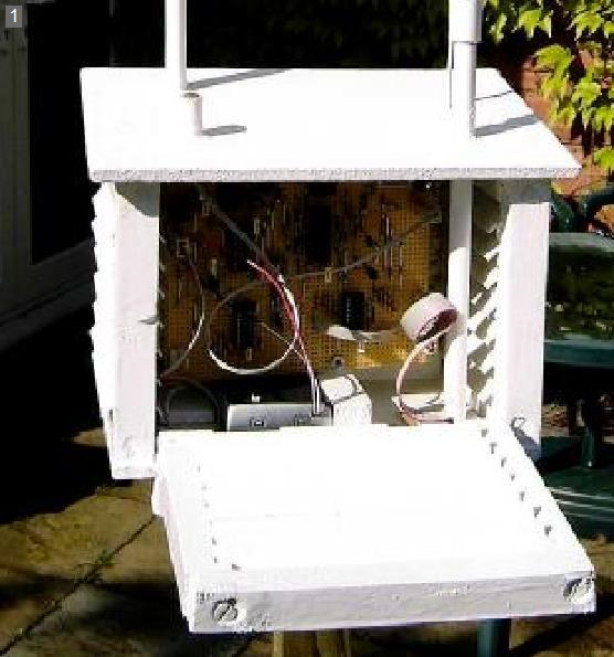
[1] The outdoor unit
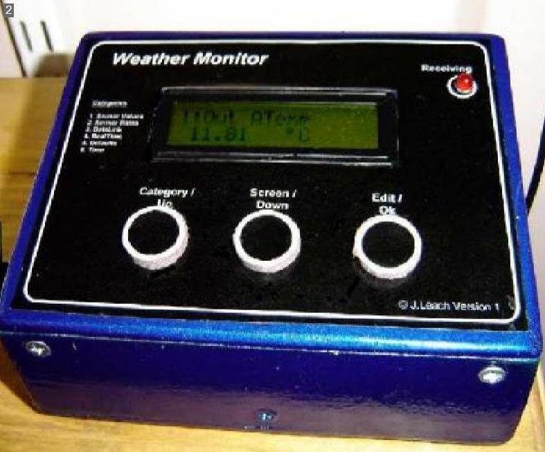
[2] The indoor unit
At a glance
The Weather Monitor system comprises an Outdoor and Indoor Unit.
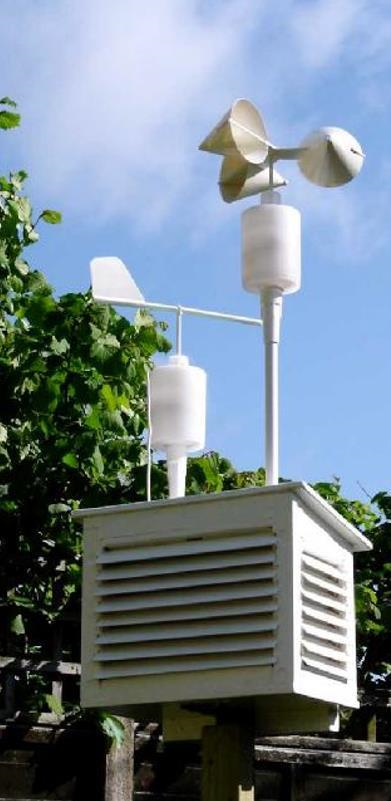
The outdoor unit collects outdoor sensor readings and transmits them at regular intervals to the Indoor Unit :
• Sensors for air and ground temperature, light, humidity, wind speed and direction.
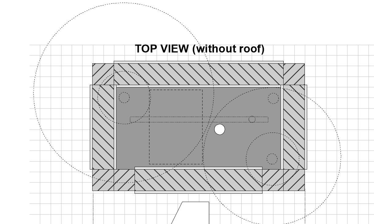
• Unit designed to maximise free airflow around sensors while also protecting from rain, birds and insects!
• 433MHz radio-transmitter, sending sensor data to the Indoor Unit at minute intervals.
• Battery powered, with a DC-DC converter to get maximum energy from the batteries.
• Power shutdown between transmissions.
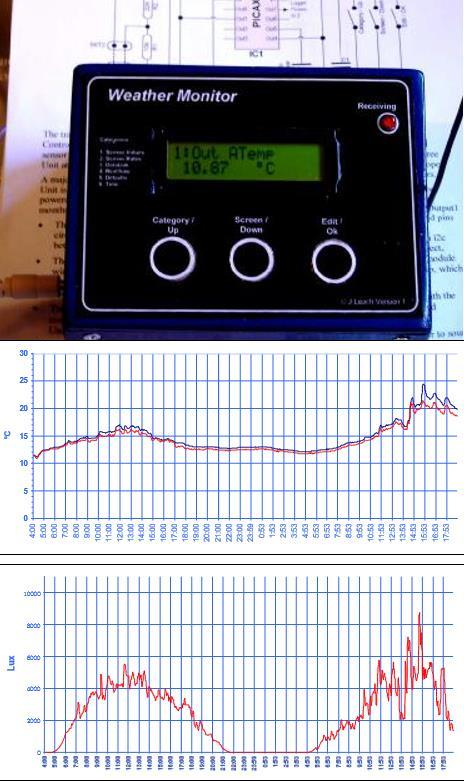
The indoor unit collects, stores, displays and uploads all sensor readings :
• On-board air temperature and pressure sensors.
• 433MHz radio receiver with antenna.
• EEPROM Memory to store at least 1 day's readings.
• Download socket to download readings to a PC.
• Programming socket to load PICAXE code.
• User-interface of LCD display, and buttons.
• Piezo-buzzer and LED indicators.
The outdoor unit collects outdoor sensor readings and transmits them at regular intervals to the Indoor Unit :
• Sensors for air and ground temperature, light, humidity, wind speed and direction.
• Unit designed to maximise free airflow around sensors while also protecting from rain, birds and insects!
• 433MHz radio-transmitter, sending sensor data to the Indoor Unit at minute intervals.
• Battery powered, with a DC-DC converter to get maximum energy from the batteries.
• Power shutdown between transmissions.
The indoor unit collects, stores, displays and uploads all sensor readings :
• On-board air temperature and pressure sensors.
• 433MHz radio receiver with antenna.
• EEPROM Memory to store at least 1 day's readings.
• Download socket to download readings to a PC.
• Programming socket to load PICAXE code.
• User-interface of LCD display, and buttons.
• Piezo-buzzer and LED indicators.
A modular design
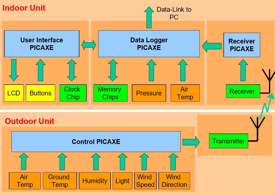
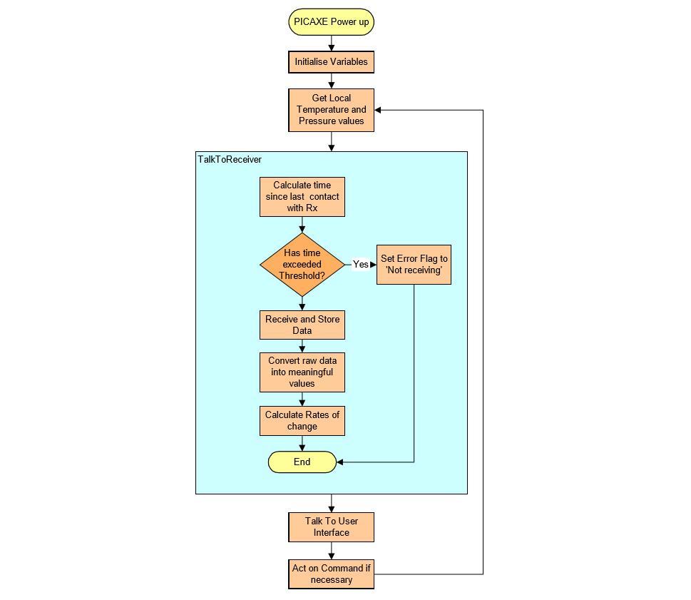
This is a block-diagram showing data-flow between all elements of the Weather Monitor system. There are five logical modules each having a separate function.
Modules in the indoor unit
There are three modules :
Working in parallel
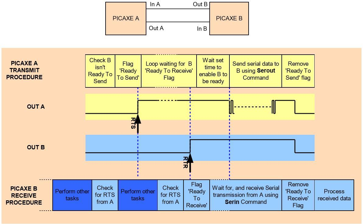
Inter-PICAXE communication (A sending to B)
It might appear that a larger spec PICAXE could replace all the three PICAXEs in the Indoor Unit, which would reduce system and circuit complexity. However the system would then suffer from a couple of undesirable problems:
• Data transmission from the Outdoor Unit could be missed while the user is interfacing to the system, or when data is being logged or sent to the PC.
• The user interface could operate erratically and hang while other tasks are being performed.
Having 3 separate PICAXEs gives each module it's own processing unit and so the modules can execute in parallel. Unfortunately though, the modules can't operate entirely independently because they have to communicate, and this interrupts their execution. This raises a classic parallel-processing scheduling problem: In order for two modules to communicate both modules must be ready for the communication. It is also desirable, or even essential, that each module isn't waiting long for the other to be ready.
There are numerous solutions to this scheduling issue, each with benefits and drawbacks.
One solution is to simply agree set times to communicate and the modules then 'meet up' at these times to chat. This sounds simple, but relies on a common time reference, is wasteful if there isn't much to communicate and adds a restriction on how fast messages can be communicated.
Another solution might be to have a separate 'message module' whose sole function is to rapidly receive and forward data with minimum waiting time. This is an attractive solution, however it adds complexity.
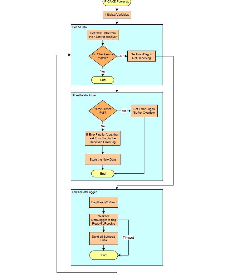
A less elegant, but simple, solution that I've used in this design is to force each module to do regular checks to see if data needs to be communicated from other modules. This introduces a code and processing overhead in each PICAXE, but with a bit of tuning a practical balance between waiting times and overhead can be achieved.
I'm sure there are other solutions too, and this would be an interesting topic to explore. To give a better understanding of this method of communication, I've shown a timing diagram for PICAXE_A sending data to PICAXE_B.
Note that the first Task for PICAXE_A is to check if PICAXE_B is ready to send. There has to be a decision about which PICAXE is the 'Master' and which is the 'Slave'. If PICAXE_B is the Master and it also wants to send data, then PICAXE_A has to change from it's sending procedure to it's receive procedure.
In reality there are variations to the send/receive procedures to suit circumstances. For example, in this project, immediately after the Data-Logger has served data to the User Interface, the User Interface replies with the current time. It's just efficient to do this while they are both talking.
Also, for the Receiver, because I've put an importance on not missing data transmissions, if the receiver is waiting for the Data-Logger to be 'Ready To Receive' but knows a transmission is imminent it 'times out' and goes back to listening for the transmission.
• Data transmission from the Outdoor Unit could be missed while the user is interfacing to the system, or when data is being logged or sent to the PC.
• The user interface could operate erratically and hang while other tasks are being performed.
Having 3 separate PICAXEs gives each module it's own processing unit and so the modules can execute in parallel. Unfortunately though, the modules can't operate entirely independently because they have to communicate, and this interrupts their execution. This raises a classic parallel-processing scheduling problem: In order for two modules to communicate both modules must be ready for the communication. It is also desirable, or even essential, that each module isn't waiting long for the other to be ready.
There are numerous solutions to this scheduling issue, each with benefits and drawbacks.
One solution is to simply agree set times to communicate and the modules then 'meet up' at these times to chat. This sounds simple, but relies on a common time reference, is wasteful if there isn't much to communicate and adds a restriction on how fast messages can be communicated.
Another solution might be to have a separate 'message module' whose sole function is to rapidly receive and forward data with minimum waiting time. This is an attractive solution, however it adds complexity.
A less elegant, but simple, solution that I've used in this design is to force each module to do regular checks to see if data needs to be communicated from other modules. This introduces a code and processing overhead in each PICAXE, but with a bit of tuning a practical balance between waiting times and overhead can be achieved.
I'm sure there are other solutions too, and this would be an interesting topic to explore. To give a better understanding of this method of communication, I've shown a timing diagram for PICAXE_A sending data to PICAXE_B.
Note that the first Task for PICAXE_A is to check if PICAXE_B is ready to send. There has to be a decision about which PICAXE is the 'Master' and which is the 'Slave'. If PICAXE_B is the Master and it also wants to send data, then PICAXE_A has to change from it's sending procedure to it's receive procedure.
In reality there are variations to the send/receive procedures to suit circumstances. For example, in this project, immediately after the Data-Logger has served data to the User Interface, the User Interface replies with the current time. It's just efficient to do this while they are both talking.
Also, for the Receiver, because I've put an importance on not missing data transmissions, if the receiver is waiting for the Data-Logger to be 'Ready To Receive' but knows a transmission is imminent it 'times out' and goes back to listening for the transmission.
Modules in the outdoor unit
The Outdoor Unit consists of a Control Module and a transmitter module.
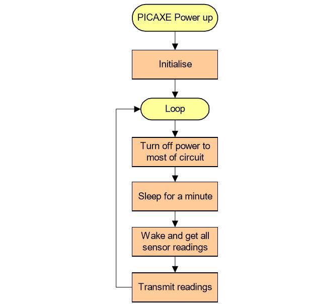
The transmitter Module needs no explanation. The Control Module uses a PICAXE18X. It gathers sensor readings and transmits them to the Indoor Unit at minute intervals.
A major consideration in the design of the Outdoor Unit is power consumption, as it needs to be battery powered and the batteries should ideally last a few months. Battery power is conserved by:
• The PICAXE shutting power down to most circuit elements and going into sleep mode between transmissions.
• The PICAXE making 'spot' readings, including wind speed (described in detail later).
• Transmitting raw data and leaving all complicated maths processing to the Indoor Unit.
Indoor Unit Circuits
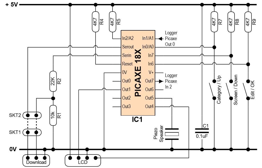 User interface circuit
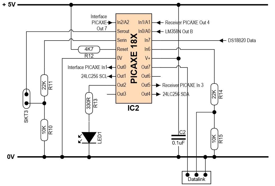 Data logger : Main circuit
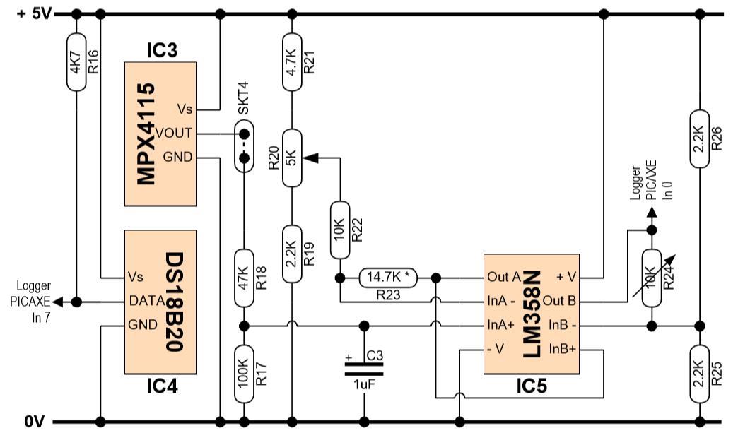 Data logger : Local temperature and pressure circuit
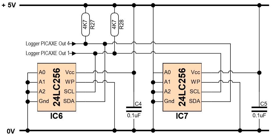 Data logger : Memory circuit
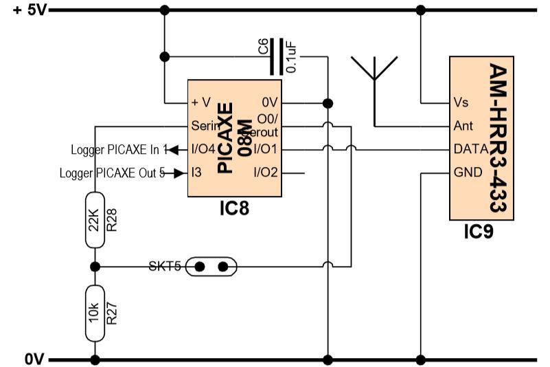 Receiver circuit
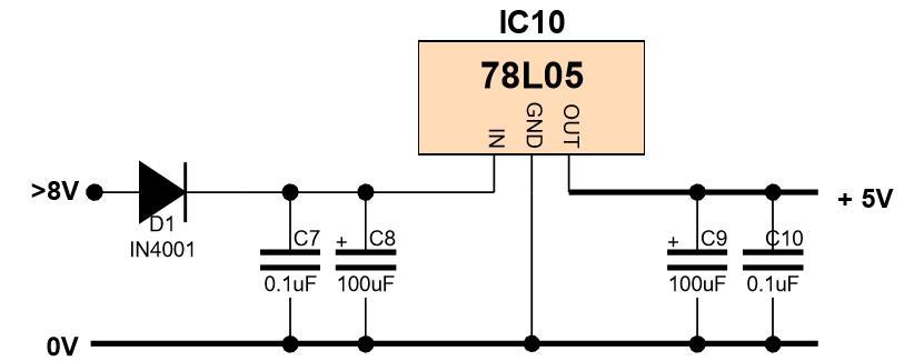 Voltage regulator circuit
Outdoor Unit Circuits
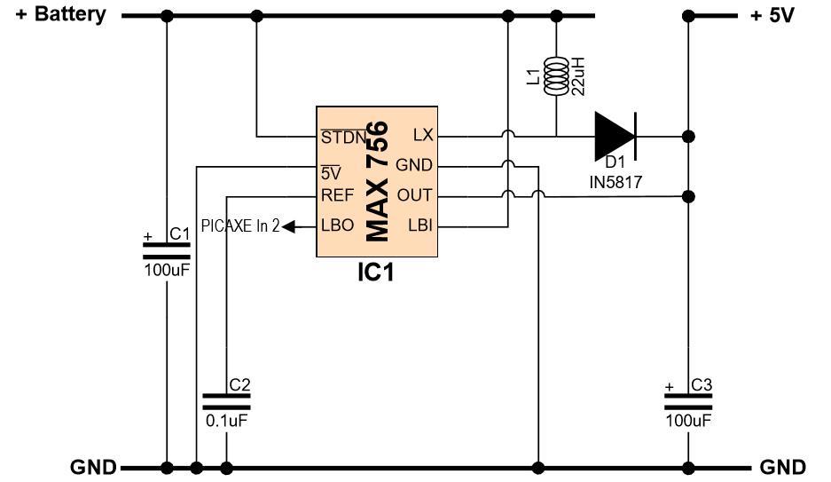 Step-up DC-DC circuit
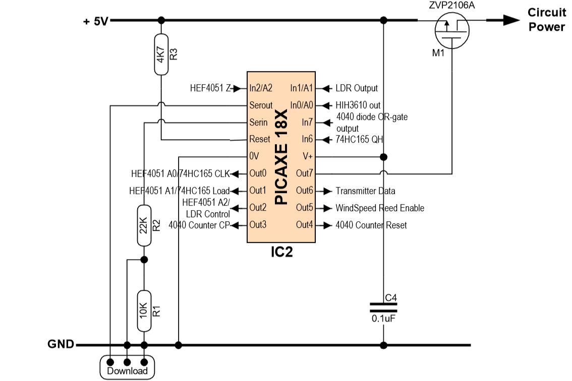 Controller circuit
 Multiplexed inputs
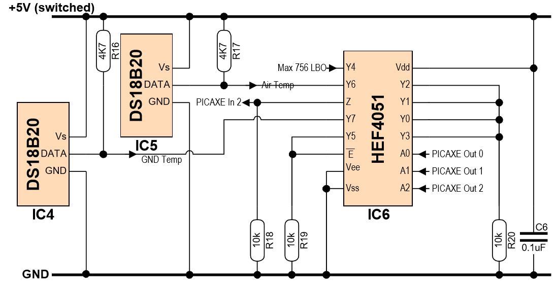
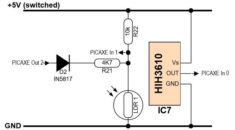 Analogue sensors
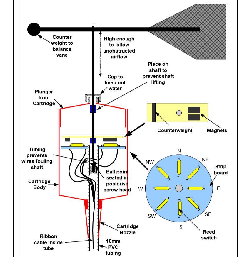
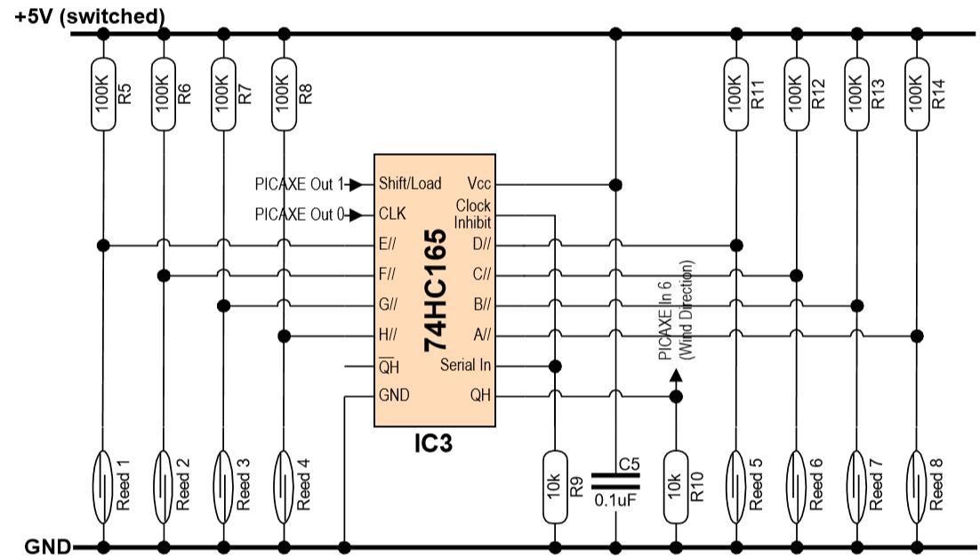 Wind direction
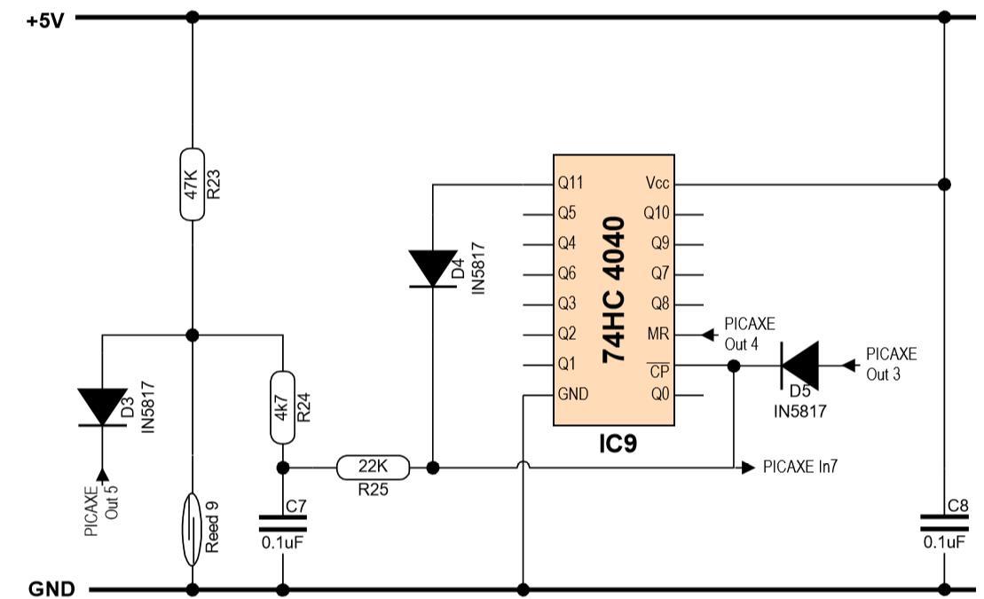 Wind speed
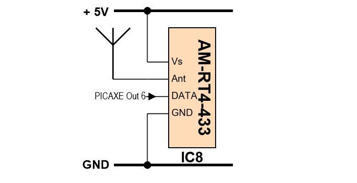 Transmitter circuit
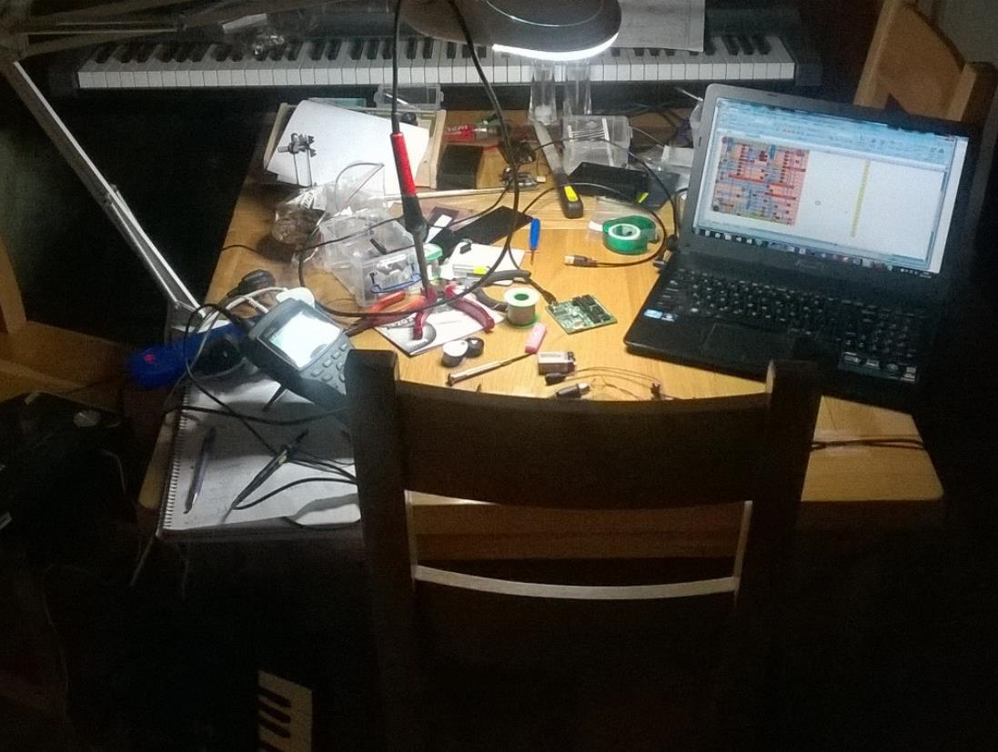
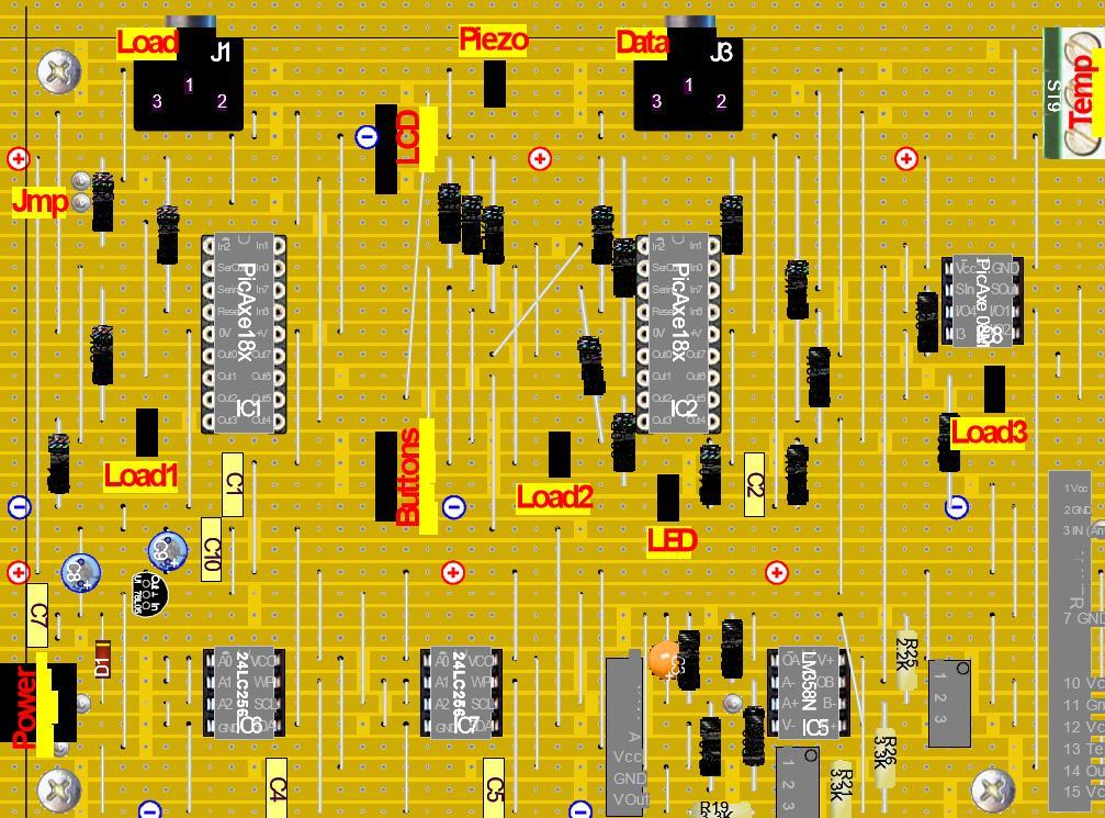
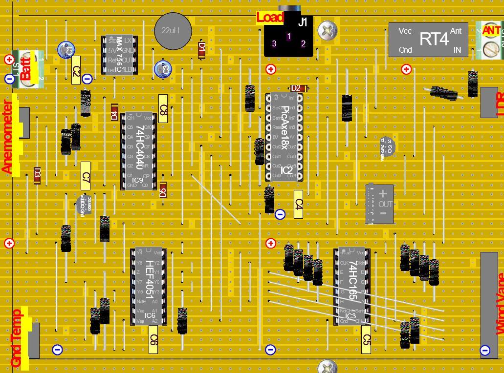
Circuit construction
Both Indoor and Outdoor Unit circuits are constructed on standard Strip-board with 36 tracks by 50 holes (although I cut the Outdoor Unit board down to size from a larger board).
The time to make the circuits should not be underestimated! Around 5 solid hours per board isn't an exaggeration, as each circuit will need to be made methodically and carefully. I cut all jumper wires to length individually, but it might be worth considering using packs of ready-cut jumper wires.
The time to make the circuits should not be underestimated! Around 5 solid hours per board isn't an exaggeration, as each circuit will need to be made methodically and carefully. I cut all jumper wires to length individually, but it might be worth considering using packs of ready-cut jumper wires.
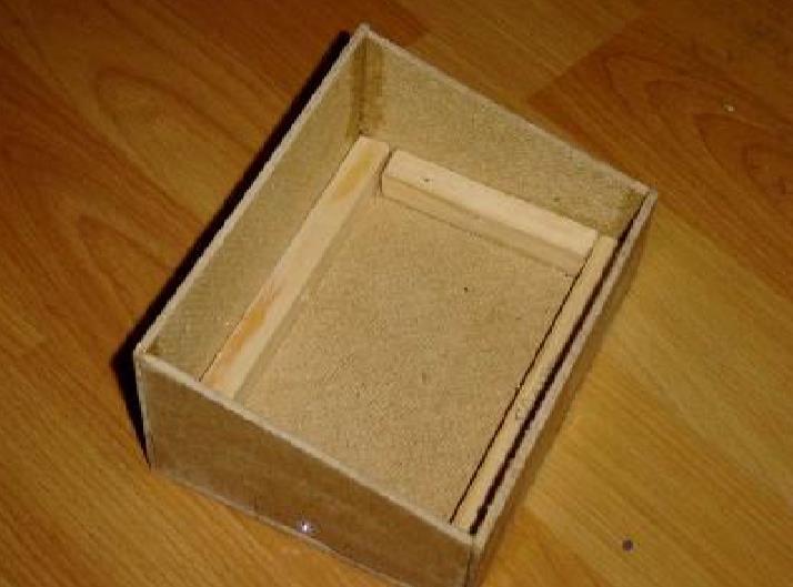
Housing it all
There are many ways to house electronic projects, and many commercially available boxes that give a good finish.
I chose to build the housings out of basic materials because it allows them to be built exactly as required, is cheap and gives a pleasing sense of achievement. A good thing is that there is nothing too critical in the way the units must be housed. I've pointed out a number of design considerations below, but there is great flexibility.
Again, don't underestimate the effort involved. My hand-made miniature Stevenson Screen with an opening door was quite an undertaking!
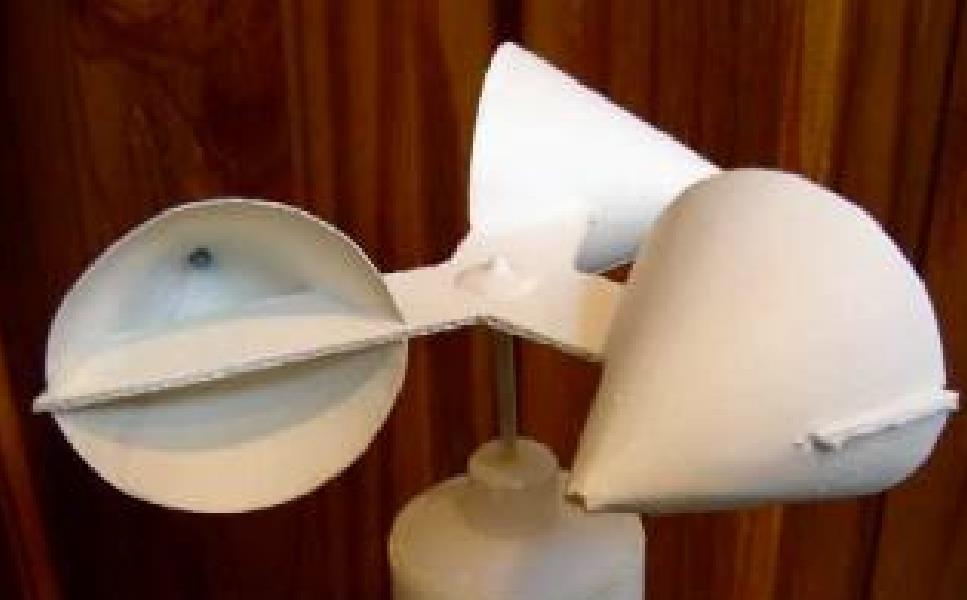
Building sturdy wind-vane and anemometer housings is also quite difficult. I'm particularly pleased with my idea to use DIY sealant-gun tubes, however there are many other ideas available on the Internet.
I chose to build the housings out of basic materials because it allows them to be built exactly as required, is cheap and gives a pleasing sense of achievement. A good thing is that there is nothing too critical in the way the units must be housed. I've pointed out a number of design considerations below, but there is great flexibility.
Again, don't underestimate the effort involved. My hand-made miniature Stevenson Screen with an opening door was quite an undertaking!
Building sturdy wind-vane and anemometer housings is also quite difficult. I'm particularly pleased with my idea to use DIY sealant-gun tubes, however there are many other ideas available on the Internet.
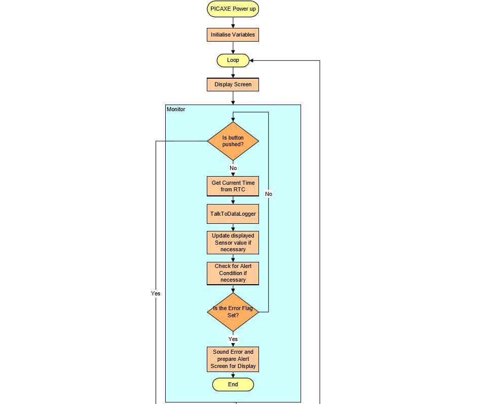
Coding it up
The coding of all the PICAXE chips took considerable effort. The code listings are separate to this article, and too long to discuss in detail, however I will give an overview here.
Outdoor Unit Performance
The Indoor Unit is made to initiate an upload to the PC by starting the Datalink Command. (I have also built in the facility for a 'realtime' tranmission of the current sensor values , but this currently isn't developed).
To receive and chart the received data, I've written a separate VBA program as part of an ExcelTM workbook called WeatherMonitorV2.xls available from my website.
To receive and chart the received data, I've written a separate VBA program as part of an ExcelTM workbook called WeatherMonitorV2.xls available from my website.
PC Software
Inspiration behind the Weather Monitor

[1] English countryside
[2] Early Plotter
I grew up in the English countryside, where the weather is often dramatic and beautiful, particularly in springtime.
Interests in both the weather and electronics lead me to some early experiments in weather readings and attempts to build recording devices with clockdriven drums and home-built servos. I progressed to building a crude stepper-controller plotter that I used to graph temperature (driven by a Spectrum computer).
There's a certain satisfaction with being able to track precise weather readings and to spot interesting trends and events. I had this dream of one day owning a barograph and being able to see the pressure changes as weather fronts passed over the house.
Many years later I decided to investigate prices and availability of Barographs on the net. Although there are many traditional Barographs out there, I began to realise I could make my own electronic version, which would be cheaper, more accurate and reliable and more fun. I eventually stumbled on the PICAXE site and realised I could go even further and make something far more ambitious.
This project has been very demanding in my time and patience, however it's also been extremely rewarding, an adventure, and has allowed me to achieve this unusual dream!
Designed using CollectAny software www.CollectAny.com